Background Information on The Pole Paddle System
Going the Distance
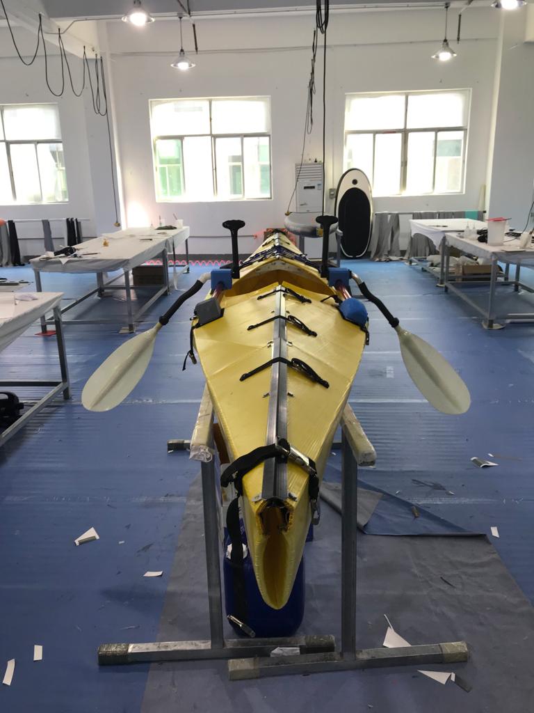
This video in high speed demonstrates how easy it is to travel great distances with the pole paddle system. If you get tired standing up and pole paddling, you can always sit down and row facing forwards. All the tests before the yellow paddle board did not include a rotating grip which improved the performance significantly.
Here are a couple of images of the first generation prototype. I made it in my garage out of HDPE plastic sheets, PVC plastic, painter extension poles on the left image and paddle board paddles cut up on the right image. I tried having the paddles at a 45 degree angle as well as 90 degrees. I finally settled on the 90 but it might be worth testing both designs as I never actually did any speed tests.
It really was one crazy design but it did the job. Obviously I've learned a lot since then.
This video explains how the pole paddle system works. This is a second generation prototype. There are two problems with this design. One, the stainless steel wheels which ride along the track cannot withstand salt water and corrode. See video below. Rubber wheels may be an option. Also I have discovered another track design covered later. The second problem is the retraction spring which loses its tensile strength upon repeated rotations. Why is there a retraction spring? The weight of the large paddle heads make it very difficult to rotate the paddles out of the water at the end of a stroke. It's much easier to rotate the paddles into the water applying pressure to the springs and then at the end of a stroke loosening the grip on the poles, letting the springs pop the paddles to their upright position and then pulling the paddles forward. A torsion spring will solve the problem of the extension spring losing tensile strength as pictured in the image below.
Here's a video of me talking about the track that is embedded in the yellow paddle board above.
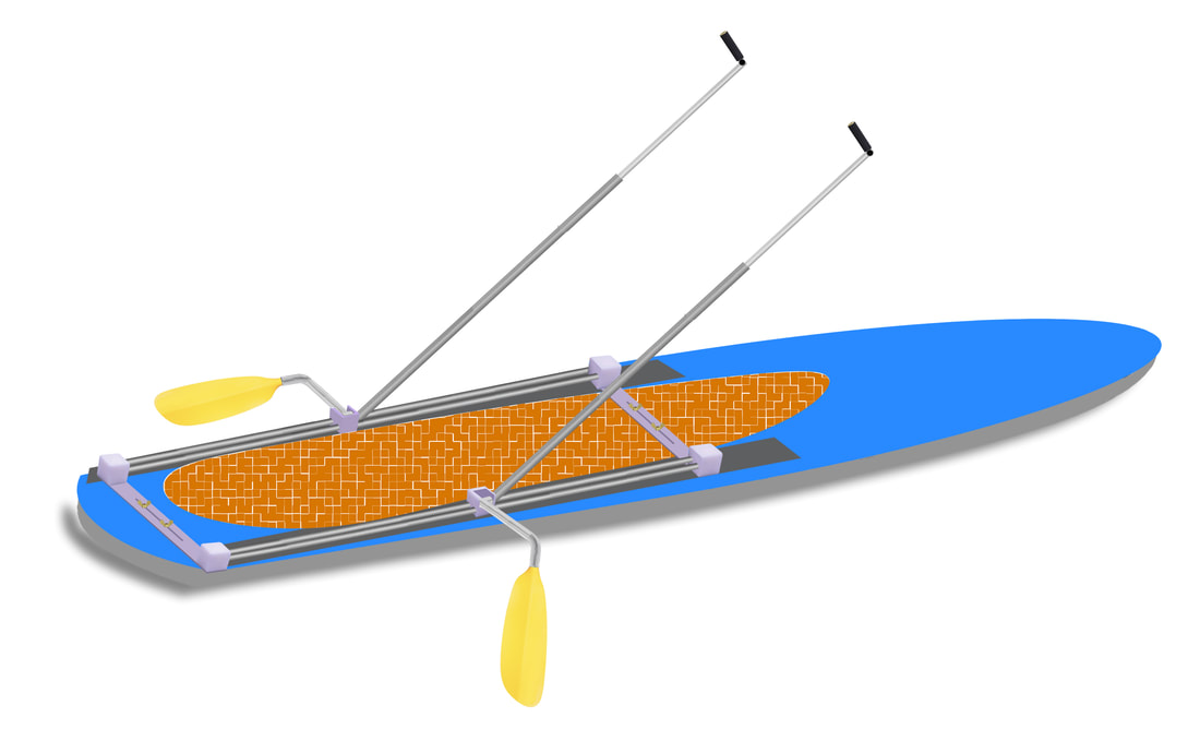
This is how the torsion spring will fit into the design.
Another look at the design showing that the paddle arm could be removable as well as where the torsion spring goes.
Components That Make Up The Pole Paddle System
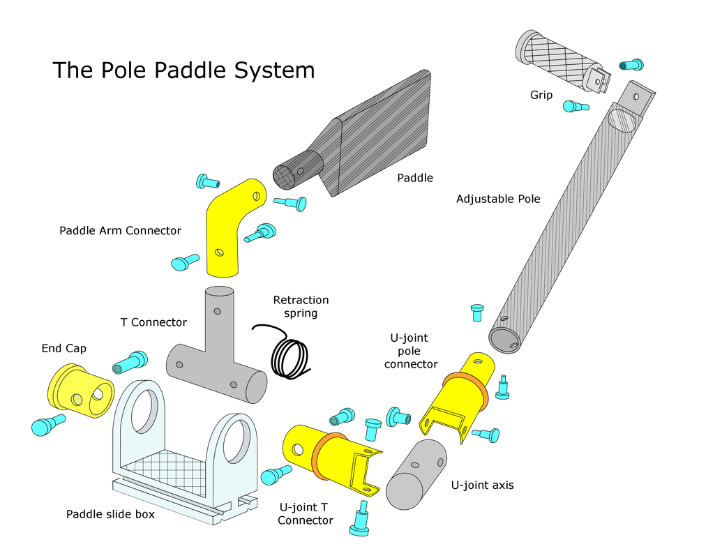
This is the design of the last prototype I made. I had the parts 3D printed. You will see me on a board in the next video demonstrating how it operates. I cover the shortcomings of this particular track design. In addition, it makes little sense to manufacture the components in this fashion as it creates the need for many injection molds, creating a large startup cost. Alternative methods should be pursued in my opinion.
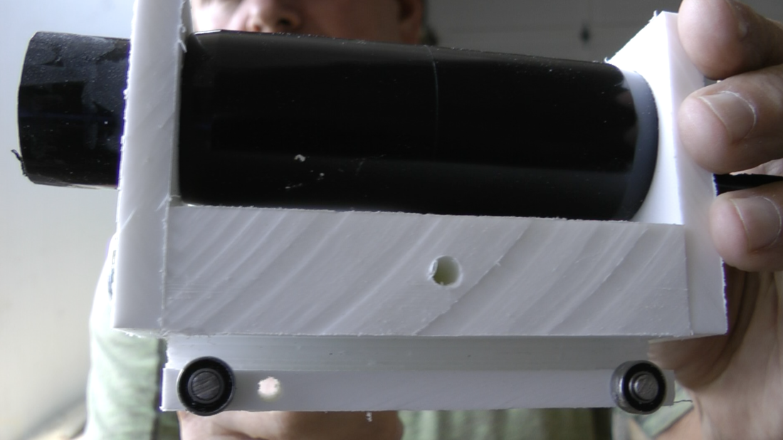
This is an end view of the track with the paddle slide box in it. The parts were 3D printed. A good design except when the pole paddle is rotated which causes friction which I cover below.
The above images are from the third generation attachable prototype which had a specially designed track for the paddle slide box to slide in. What the design did not account for is that when the paddles are rotated into the water against the spring, extreme friction occurs and the paddle slide box will not slide properly. The picture below shows how it theoretically performs but such is not the case, it binds.
If rubber wheels were used. this is an end view of how the wheels would ride on the track when rotation was applied to the pole paddles.
If lightweight paddle heads are used, then it is possible to manually rotate the paddles out of the water at the end of a stroke as explained in the above video. It is my belief that the retraction spring design is superior because larger paddle heads will be more effective in producing power and while I was able to easily rotate the paddles out of the water, others such as women and kids might find it difficult.
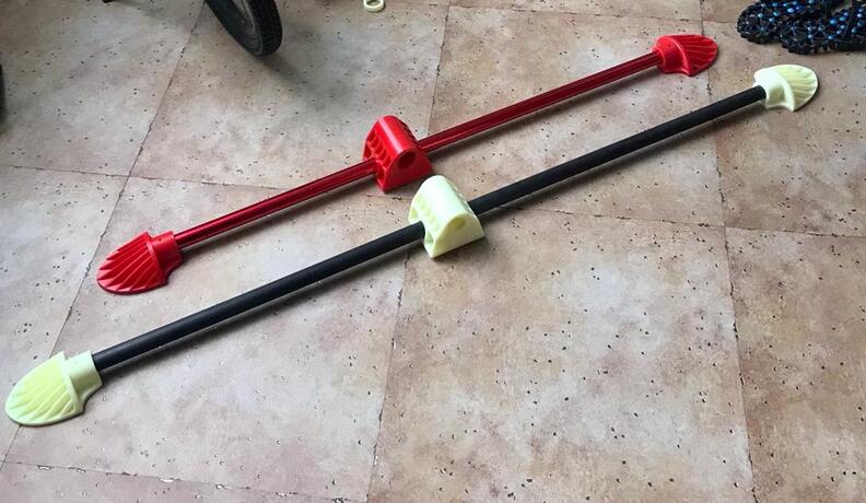
Here is another image of the pole paddle system showing that the paddle heads can be interchangeable, larger heads for adults, smaller heads for children.
The U-joint in the original design was machined out of PVC plastic furniture parts and a plastic rod.
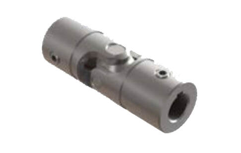
This is a U-joint manufactured by Belden which can possibly replace the machined plastic parts. They have many designs to choose from.
The rotating paddle arm assembly was also made out of PVC plastic furniture parts. I believe it would be best to manufacture the arm from aluminum tubes and then possibly carbon fiber in the future.
In one of the prototypes I modified extension poles made for painters as seen on the left. In the model seen above with the yellow paddle board I used Jimmy Styks carbon fiber paddle board paddles which I cut up. The image on the right shows a Jimmy Styks paddle.
Whatever type of adjustable pole is used, the locking mechanism must be similar to the above image because a round adjustable pole with a lock will come loose because of the repeated rotations.
The above images are of the grip which attaches to the adjustable pole. A rubber grip slides over it. This part can possibly be CNC'd rather than injection molded reducing costs (I believe). Or perhaps a grip might be available off the shelf.
Here is another video explaining the operation and showing all the parts that were 3D printed. Between this video and the first video viewed you should have a complete understanding of all the components involved in the design.
New Track Design
This is the demo video from the Drylin website. They have many sliding bearings which I believe could be used for the Supski.
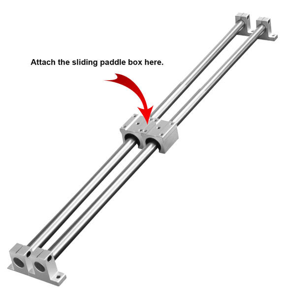
Here is one possibility for the tracks. Two bearing are required to be side by side because when the pole paddles are rotated into the water a single bearing would not hold the system in proper registration.
Here is another possible track so long as when you rotate the pole paddles that the friction is not too great. There may be an advantage to a design like this because Velcro can be put underneath its entire length rather than just at the ends to attach it to a board. If the track is going to attach to an paddle board someone already owns whose length is shorter than necessary for the user to get a complete stroke, you may want to have the track extend over the back end of the board so the user doesn't stand too far forward and the paddle board nose dive into the water. I hope this is clear.
The image on the left shows how the user is too far forward and the one on the right shows the track extending off the end of the board.
An 11 1/2' board should be able to handle a complete stroke when used by a man. A 10 1/2' board should be OK for a woman. These lengths of boards should be verified as I don't remember all the lengths of the boards I used while testing prototypes.
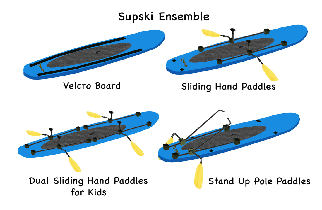
Here's a concept drawing of the tracks attached to a dedicated Velcro board. In this case the tracks wouldn't have to hang over the end. You can see I have drawn a strip to connect the two tracks. This is to hold them in place and keep them from moving when you rotate the paddles into the water.
Here's a artist conception I made with the tracks built into a hard board. It certainly can have a classy look and command a higher price. It would have to be determined what kind of track would be embedded in the board. One board manufacturer I spoke to several years ago thought a hard board was a bad idea because if someone fell off the board and landed on the poles, it could crack the board. So there's that.
Rowing with The Supski
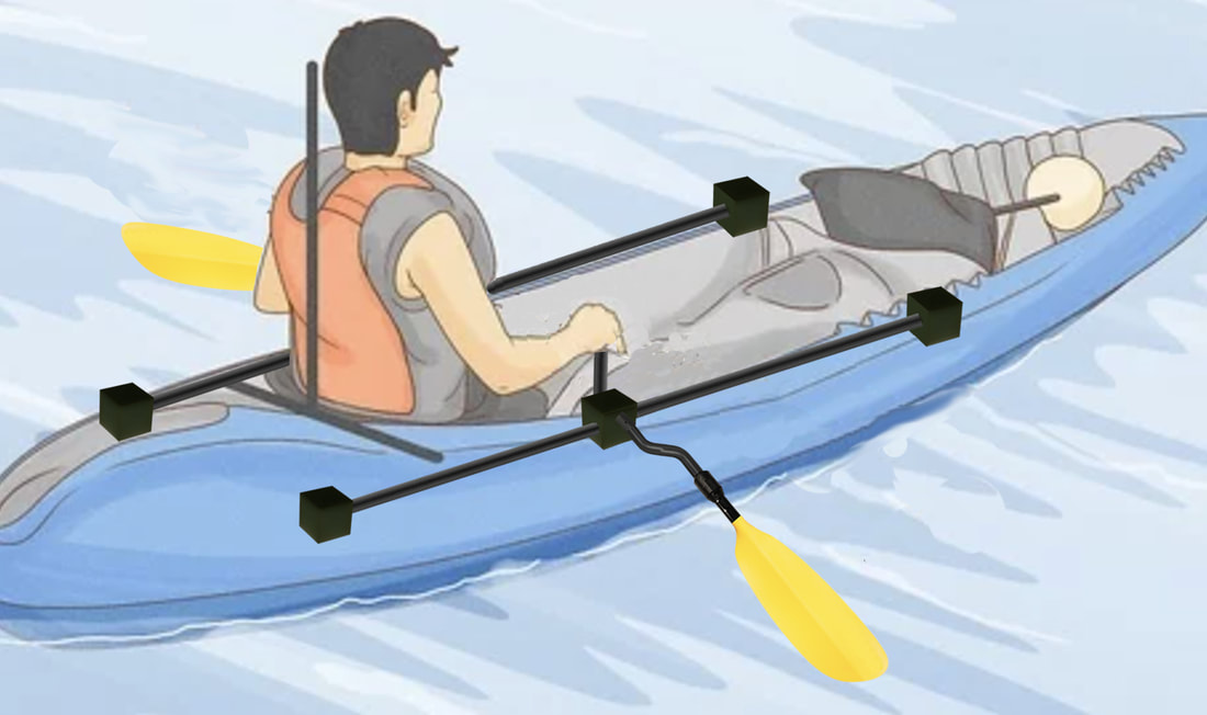
It is also possible to row on the Supski. The ability to sit down and row can be great for paddle boarders when paddling into a stiff breeze.
Another concept would be to have an attachable sliding chair which would allow the user to develop even more power, all the time while rowing facing forward.
In Summary
Hopefully I have provided you with sufficient information about the design of the Supski and you will be able to create a finished sellable product. I am available at any time to discuss the design and anything I may not have covered here. I look forward to seeing the Supski Pole Paddle System coming off the assembly line in the not too distant future.